STAFF:
List of Machinery:
|
Make |
|
|
Model |
Not Available |
|
Title of the related experiment: |
To produce a square hole/slot on a wood piece |
|
A brief explanation of the usage of the said equipment |
A stationary chain mortiser is a tool designed to cut square holes into a piece of wood, often to create mortise and tenon joints or post and beam fittings. Like other mortisers, the chain mortiser is designed to cut material squarely, which drill bits often cannot do. Unlike other mortisers, chain mortiser machines can quickly remove a significant amount of material, and the chain itself can be plunged deep into the wood to create deeper cuts. The chain runs around a bar, much like the design of a chainsaw, but usually on a smaller scale. The wood is placed on the machine's work surface and is usually clamped. A hand lever is provided on a drill press and used to drop the chain and bar to the piece of wood on the work surface. The machine may feature a depth gauge to control how deep the chain cuts. With this setup, students should be able to: · Run the machine to create square holes. ·
|
|
Make |
International Machine Tool |
|
Model |
MT-D |
|
Title of the related experiment: |
Drilling for Pattern |
|
Brief explanation on usage of the said equipment |
This universal movements of the tool head permit the drill tool located at any desired position over the stationary work piece. The head containing electric motor, V-pulleys and V-belt which transmit rotary motion to the · Run the machine at low speed and observe the motions, which control the shapes of the surfaces produced. · Note particularly the features, which control the geometrical form of the surface. · Record the obtainable speed and feed values. |
|
Make |
G. S. PAIK |
|
Model |
BS24 |
|
Title of the related experiment: |
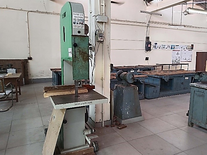
The band saw machine for wood cutting in making patterns |
|
A brief explanation of the usage of the said equipment |
The band saw machine is used to perform wood-cutting operations in making patterns which are used in a casting process. In a bandsaw, workpieces are fed into the cutting edge of the machine. The bandsaw machine cuts by drawing a continuous metal band across the workpiece. The bandsaw blade is supported and driven by a drive wheel and an idler wheel. Because each tooth is a precision cutting tool, accuracy can be held to close tolerances. This eliminates or minimizes many secondary machining operations. In addition, chip removal is very fast. An electric motor drives a typical vertical bandsaw machine through a belt transmission. The belt allows adjustment of the blade speed. The blade rotates on a fixed track between the idler wheel mounted above the work table, and the drive wheel mounted beneath the work table and cuts into the side of the stock. The stock is moved against the blade to cut. The table can be tilted front-to-back or sideways to allow the mitred cuts. With this setup, students should be able to: · Identify the machine controls along with the blade tension indicator. · Adjust the speed of the blade using the speed adjust dial to the blade speed required for the material being used. · Usage of work holding jaw whenever possible. · Check the final dimensions of the workpiece as per desired dimensions achieved. |
|
Make |
G. S. PAIK |
|
Model |
BS12 |
|
Title of the related experiment: |
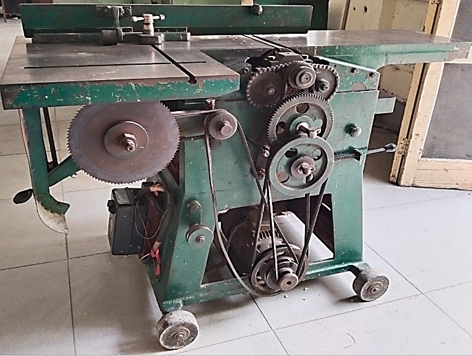
Hand Machine Planner machine for wood cutting in making patterns |
|
A brief explanation of the usage of the said equipment |
A thickness planer consists of three elements: a cutter head which contains the cutting knives; a set of rollers which draw the board through the machine; and a table which is adjustable relative to the cutter head to control the resultant thickness of the board. Some portable thickness planers differ slightly in that the table is fixed, and the cutter head/feed roller assembly is adjusted. Industrial thickness planers can accept very wide boards and remove large amounts of material in a single pass. These machines are driven by powerful motors. Recently, a range of lightweight, portable thickness planers have become available that use cheaper, noisy, universal motors rather than induction motors and are much less expensive than an industrial ones. With this setup, students should be able to: · Identify the machine controls along with the blade tension indicator. · Adjust the speed of the blade using the speed adjust dial to the blade speed required for the material being used. · Usage of work holding jaw whenever possible. · Check the final dimensions of the workpiece as per desired dimensions achieved. |
|
Make |
MLB |
|
Model |
MUFORD |
|
Title of the related experiment: |
Woodturning Lathe machine for wood cutting in making patterns |
|
A brief explanation of the usage of the said equipment |
A woodturning working lathe rotates a cylindrical workpiece along its axis and removes material from the workpiece to form it into a specific shape. The cutting tools usually are hand-held against support and moved in and out and back and forth along the surface of the work by hand to form a shape like a table leg. Because of the inherent rotational nature of a lathe, the vast majority of the work produced on it is cylindrical. Despite this, the lathe is an extremely versatile machine capable of producing a surprising variety of objects used mainly as component parts of mechanical systems. Wood lathes are smaller and simpler than their metal counterparts. They don't use as much power as metal lathes, but wood lathes are highly effective at manipulating wooden workpieces. With this setup, students should be able to: · Identify the machine controls of the woodworking lathe. · Adjust the speed and feed of the woodworking lathe machine. · Manufacture of the wooden parts used for pattern in casting. · Check the final dimensions of the workpiece as per desired dimensions achieved. |